The term ‘flow’ can generally be applied in three distinct circumstances: Volumetric flow is the commonest and is used to measure the volume of material passing a point in unit time such as m3s-1. It may be indicated at the local temperature and pressure or normalized to some standard conditions using the standard gas law relationship. Mass flow is the mass of fluid passing a point in unit time e.g. kgs-1. Velocity of flow is the velocity with which a fluid passes a given point. Flow measurement is an important component in the industry; Flowmeters are used for liquid, gas and steam measurements. Whilst modern techniques of flow measurement like Coriolis are increasingly becoming popular, flowmeters based on the traditional flow measurement techniques such as the differential pressure meters still play a key role in the industry.
Basis of Operation of Differential Pressure Flowmeters
If a constriction is placed in a pipe as illustrated in the figure below, the flow must be higher through the restriction to maintain equal mass flow at all points; the increase in velocity at the restriction causes the static pressure to decrease at this section, and a pressure difference is created across the element. The difference between the pressure upstream and pressure downstream of this obstruction is related to the rate of fluid flowing through the restriction and therefore through the pipe. Basically a differential pressure flowmeter consists of two basic elements: an obstruction to cause a pressure drop in the flow i.e. a differential producer and a method of measuring the pressure drop across this obstruction – differential pressure transducers.

The common differential pressure flowmeters include the orifice plate, venturi tube and the nozzle. In this article, we look at these three common differential pressure flowmeters, their principles of working, application capabilities and limitations. Other differential flowmeters include: segmental wedge, V-cone, elbow and Dall tube.
Orifice Plate
An orifice plate in its simplest form is a thin steel plate with a circular orifice of known dimensions located centrally in the plate. This is referred to as concentric orifice plate. The plate can be clamped between the flanges in a pipeline has demonstrated below:

The increase in velocity of the fluid that occurs as it passes through the hole in the plate results in a pressure drop being developed across the plate. After passing through this restriction, the fluid flow jet continues to contract until a minimum diameter known as the vena contracta is reached.
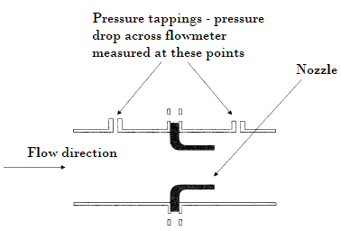
Let’s consider the figure below:

From Bernoulli’s equation and the conservation of mass principle:
V1A1ρ = V2A2ρ Equation 1
Rearranging the above equation and substituting for V2 gives:

This shows that the volumetric flow rate of fluid Q can be determined by measuring the drop in pressure (P1 – P2) across the restriction in the pipeline – the basic principle of all differential pressure flowmeters.
If equation 2 is used to calculate volumetric flow rate from a measurement of the pressure drop across the orifice plate, then an error would result. This is because A2 should strictly be the area of the vena contracta, which is apparently unknown. Furthermore, turbulence between the vena contracta and the pipe wall results in an energy loss that is not accounted for in this equation.
To overcome the problems caused by the practical application of equation 2, two empirical determined correction factors are added. After some reorganization, equation 2 can be written as:

Where ρ = Density of the fluid upstream of the orifice plate.
d = Diameter of the hole in the orifice plate.
β = Diameter ratio d/D, where D is the upstream internal pipe diameter.
The two empirically determined correction factors are C, the discharge coefficient, and ε the expansibility factor. C is affected by changes in the diameter ratio, Reynolds number, pipe roughness, the sharpness of the leading edge of the orifice, and the points at which the differential pressure across the plate are measured. Nonetheless, for a fixed geometry, it has been shown that C is only dependent on Reynolds number and so this coefficient can be determined for a particular application. ε is used to account for the compressibility of the fluid being monitored.
Both C and ε can be determined from equations and tables in a number of internationally recognized documents referred to as standards. These standards specify C and ε and also the geometry and installation conditions for the square-edged orifice plate, Venturi tube and nozzle, and are essentially a design guide for the use of the commonly used types of differential pressure flowmeters.
Installation recommendations are intended to ensure that fully developed turbulent flow conditions exist within the measurement section of the flowmeter. The most commonly employed standard in Europe is ISO 5167-1, while in the US, API 2530 is the most popular.
Equation 3 illustrates possibly the greatest strength of the orifice plate, which is that measurement performance can be confidently predicted without the need for calibration if the device is manufactured, installed, and operated in accordance with one of the international standards. Additional, it is inexpensive to manufacturer this device, it has no moving parts, is reliable, simple in operation and can be used for metering most clean gases, liquids and steam.
The main disadvantages of the orifice plate are its poor turn-down ratio/limited range and sensitivity to flow disturbances. The fact that fluid flow rate is proportional to the square root of the measured differential pressure limits the range of a one plate/one differential pressure transmitter to about 3:1. The required diameter ratio (also referred to as beta ratio) of the plate depends on the maximum flow rate to be measured and the range of the differential pressure transducer available. Lastly this device suffers from high irrecoverable pressure loss and has critical installation requirements.
The Venturi Tube
The classical venturi tube is shown in the figure below. It comprises of a cylindrical inlet section, followed by a convergent entrance into a cylindrical throat and a divergent outlet section.

As figure 1.4 above shows, a restriction is introduced into the flow in a more gradual way than the orifice plate. The resulting flow through a Venturi tube is closer to that predicted in theory by equation 2 and so the discharge coefficient C is much nearer unity, being typically 0.95. Furthermore, the permanent pressure loss caused by the Venturi tube is lower, but the differential pressure is also lower than for an orifice plate of the same diameter ratio. The smooth design of the Venturi tube means that it is less sensitive to erosion than the orifice plate, and thus more suitable for utilization with dirty gases or liquids. The Venturi is also less sensitive to upstream disturbances and therefore requires shorter lengths of straight pipework upstream of the meter than the equivalent orifice plate or nozzle. The Venturi tube has long-term reliability and no moving parts especially when compared to rotating mechanical flowmeters.
Just like the orifice plate and nozzle, the design, installation and use of the Venturi tube is covered by several international standards.
The major downsides of the Venturi tube flowmeter are its size and cost. It is more difficulty, and therefore more expensive to manufacture Venturi tube than the orifice plate. Since a Venturi tube can be typically 6 diameters long, it can become challenging to use with larger pipe sizes, with associated maintenance of upstream and downstream pipe lengths also becoming an issue.
Generally the Venturi tube is used for applications where there is high solids content or where high pressure recoverable is desirable. The venturi tube is inherently a low head-loss device and can result in an appreciable saving of energy.
The Nozzle
The nozzle combines some of the best features of the orifice plate and Venturi tube. It is compact and yet, because of its curved inlet, has a discharge coefficient close to unity. There are several designs of nozzle, but one of the most commonly used in Europe is the ISA-1932 nozzle, whilst in the US, the ASME long radius nozzle is more popular. Both of these nozzles are covered by international standards.

The smooth inlet of the nozzle means that it is more costly to manufacture than the orifice plate, as the curvature of the inlet changes with diameter ratio, although it is less expensive than the Venturi tube. The device has no sharp edges to cause changes in calibration and thus is well suited for use with dirty and abrasive fluids. The nozzle is also commonly used for high-velocity, high-temperature applications such as steam metering.
Installation Requirements – Differential Pressure Flowmeters
The performance of most flowmeter technologies significantly depends on the installation. Installation requirements for differential pressure devices are quite critically important. It is advisable to install primary elements as far downstream as possible from flow disturbances such as bends, valves, and reducers. Standards contain detailed recommendations for the minimum straight lengths of pipe required before and after the flowmeter, in order to ensure a fully developed flow profile. Straight lengths of pipe are required after the flowmeter because disturbances caused by a valve or bend can travel upstream and thus also affect the installed flowmeter. If it is not possible to fit the recommended lengths of straight pipe before and after the flowmeter, then the flowmeter must be calibrated once it is installed.
The table below gives examples of installation requirements taken from ISO 5167-1.
Table 1: The minimum straight lengths of pipe required between various fittings and an orifice plate or venturi tube as recommended in ISO 5167-1, to ensure a fully developed profile exists in the measurement section. All lengths are multiples of the pipe diameter.
| Upstream of the flowmeter | Downstream of the flowmeter | ||||
| Diameter Ratio β | Single 90° bend | Two 90° bends in the same plane | Two 90° bends in the different planes | Globe valve fully open | For any of the fittings shown to the left |
| 0.2 | 10 | 14 | 34 | 18 | 4 |
| 0.4 | 14 | 18 | 36 | 20 | 6 |
| 0.6 | 18 | 26 | 48 | 26 | 7 |
| 0.8 | 46 | 50 | 80 | 44 | 8 |
The presence of a rotating flow or swirl is another major challenge one might face during installation. This condition distorts the flow velocity profile in a very unpredictable way and is obviously not desirable. Situations like two 90° bends that create swirl should rather be avoided. If this is not possible to achieve practically, then swirl can be removed by placing a flow condition/flow straightener between the source of the swirl and the flowmeter. However since the flow conditioners obstruct the flow, they produce an unrecoverable pressure loss, which in general increases with their capability.
Performance Characteristics & Applications of Differential Pressure Flowmeters
Choosing the best flowmeter for a particular application can be a daunting task. The major factors that influence the selection are: the required performance, the properties of the fluid to be metered, the installation requirements, the environment in which the instrument is to be used and the cost.
Compared to other flowmeter types, these differential flowmeters (orifice plate, venturi tube and nozzle) only have moderate accuracy, typically ±2% of reading; however this can be enhanced if the device is calibrated after installation. When calculating the cost and performance of a differential pressure flowmeter, both the primary element and the differential pressure transducer should be considered. Even though the orifice plate is the cheapest of the primary elements, the cost of the fitting needed to mount it in the pipeline, particularly if on-line removal is required, can be significant.
Since all these three flowmeters have similar accuracy, one strategy to employ when selecting the most appropriate instrument is to decide if there are good reasons for not using the cheapest flowmeter that can be used over the widest range of pipe sizes (orifice plate). When permanent pressure loss is important, the Venturi tube should be taken into account, although the high cost of this meter can only be justified when large quantities of fluid are being metered. For high-temperature or high-velocity applications, the nozzle should be considered under these conditions, which is more predictable than the orifice plate. For metering dirty fluids, either the Venturi tube or the nozzle should be considered in preference to the orifice plate, the choice between the two depending on cost and pressure loss requirements.
The table below shows the performance characteristics and the main application areas of the square-edged orifice plate, Venturi tube and nozzle flowmeters.
Table 2: Performance & Applications of Common Differential Pressure Flowmeters
| Performance | Applications | |||||||||
| Typical un-calibrated accuracy | Typical range | Typical pipe diameter (mm) | Permanent pressure loss | Comparative cost | Clean gas | Dirty gas | Clean liquid | Slurry | Steam | |
| Orifice Plate | ±2% | 3:1 | 10-1000 | High | Low | Yes | No | Yes | No | Yes |
| Venturi Tube | ±2% | 3:1 | 25-500 | Low | High | Yes | Maybe | Yes | Maybe | Maybe |
| Nozzle | ±2% | 3:1 | 25-250 | High | Medium | Yes | Maybe | Yes | No | Yes |
Apart from the differential producer, the other key element of a differential pressure flowmeter is the transducer required to measure the pressure drop across the pressure producer. The transducer is part of a unit known as a transmitter, which converts differential pressure, static pressure and ambient temperature measurements into a standardized analog or digital signal output.
The correct selection and installation of the differential pressure transducer plays a key role in determining the accuracy of the flow rate measurement. The key factors that should be taken into account when choosing a differential pressure transducer for a flow measurement application are: the differential pressure range to be covered, the accuracy required, the maximum pipeline pressure, and the type and temperature range of the fluid being metered.
Related Articles and Resources:
- How to Connect a DP (Differential Pressure) Flow Sensor to a DP Transmitter
- Installation Considerations of an Orifice Plate Flow Sensor
- The Ultimate Guide to Industrial Flow Measurement
- The Principle of Operation of a Vortex Flowmeter
- How to Choose the Perfect Thermal Mass Flow Meter
- Impeller Flowmeters: Features, Installation Considerations & Uses
Leave a Reply
You must be logged in to post a comment.